
Resources
Integrating Hot Runner Mold Construction
Realize time and cost saving benefits from the use of integrated systems when compared to traditional hot runner manufacturing methods.
Hot runner molds are inherently complex. They have to bring together time, temperature, flow and the pressure of plastics operating on rapid cycles. The mold needed to accomplish this can be complicated, but with straightforward planning, the process of building a hot runner mold can be a relatively simple one.
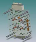
Figure 1: Drawing illustrates four-cavity hot half mold design. Figures courtesy of PCS Company.
Traditionally, the process of hot runner mold building involves having the mold base and the hot half manufactured by different suppliers and then fitted together onsite, but there is another approach: an integrated mold building process.
An integrated process brings together—under one roof—all of the materials and components to construct a complete hot runner system. An integrated mold building process can offer a host of efficiencies and avoid problems associated by having mold bases and hot halves manufactured by different suppliers.
The original design of a plastics part can come from either the molder or a part designer affiliated with the molder. Changes to the part and/or the mold design can be made at any time, right up to the start of production. However, there has to be some discipline in the process in order to move from design to production. It has often been said that a finished part will never see the light of day unless someone locks up the design engineers and starts production.
Every effort should be made to minimize last minute design changes. Changes can affect production of the hot half, the mold base or both. In any event, construction of the mold base and the hot half by one builder can accommodate inevitable changes more efficiently.
Theoretically, a hot half and mold base produced from the same set of drawings should fit together perfectly. For a host of reasons, when multiple suppliers are involved, many issues can arise. When both elements are built by the same supplier, putting responsibility in one place guarantees that the mold base and the hot half will fit together as designed. It also is important that cavities be interchangeable, so that a cavity that develops problems, for whatever reason can be readily replaced and production can continue. Figure 1 illustrates a basic four-drop, hot-half design.
Mold Base Components
P20 is perhaps the most widespread choice of steel for the mold base and hot runner plates. In addition, modified P20 pre-hardened chromium/molybdenum alloyed steel, with good polishing and texturing properties, supplied at 285-340 Brinell hardness is often used. When steel, other than P20 is needed, the choice would take into account machinability, durability, thermal conductivity and availability.
|
Nozzle and Control Module Technology Maintenance considerations should center on ease of nozzle replacement without disassembling the entire hot half. Front loaded heaters and separate thermocouples make for easy replacement and will minimize downtime while maximizing tool productivity. The nozzle tip and the resulting vestige can be key when considering the cosmetic design of the part. Valve gates, bush nuts, open nuts and sprue nuts are combined with a nozzle to get the desired vestige. Again, maintaining the desired temperature throughout the nozzle aids in creating the desired vestige. When choosing a control module a unit that provides process temperature, and also can provide amp draw and set point temperature will give the operator the greatest flexibility. A control unit that provides a choice of Centigrade or Fahrenheit temperature measurements and J or K thermocouple options are preferable, as well as one that has a 100-percent boost power button that directs high heat to the nozzle for a few seconds to melt freeze off and return to free flow of the resin. A bumpless transfer feature provides backup to the automatic temperature control settings. If a thermocouple should fail, controllers with bumpless transfer will convert from automatic to manual mode, while storing the process settings. This allows tools to continue running until the faulty thermocouple can be replaced. |
An integrated systems builder takes responsibility for acquiring and installing all components, such as hot runner nozzles (see Nozzle Technology Sidebar) and electronic hot runner controls. Assembly and testing are the final steps, after which the mold is ready for installation in the processor’s injection molding machine. Components such as side locks, pins, sleeves and water fittings can pose complications when mold manufacturing is multi-sourced. These complications are easily addressed when an integrated-system supplier builds the entire system. Figure 2 shows the base half and the hot half of a two-drop mold that illustrates the integrated system.
Some Pitfalls of Multiple Sourcing
The following example illustrates the pitfalls of ordering a mold from multiple suppliers and points to the benefits of using one source for both the hot half and mold base.
Suppose that ABC Company wants to order an eight-drop hot runner system and a mold base for a rush job. Targeted delivery for the finished tool is eight weeks.
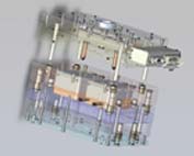
Figure 2: The base half and the hot half of a two-drop mold illustrate the integrated system.
ABC wants to get quotes from three competing sources. ABC sends engineering part drawings in 2-D format with specifications to the three potential suppliers. The part drawings are then sent to ABC’s mold designer, requesting preliminary design completion in one week.
A quote from one hot runner supplier comes in the next day. Nothing is received that day from the other competing hot runner suppliers. Finally, on day three the other hot runner quotes arrive.
The following week ABC’s mold designer completes the preliminary mold design, which is sent out for quotations. Mold base suppliers send in quotes over the next three days. Mold drawings are then sent to the hot runner suppliers and quotes are finalized, each committing to a delivery date.
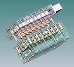
Figure 3: This 32-drop integrated system combines the base half and the hot half.
ABC selects a hot runner supplier out of the three competitors and issues the purchase order, requiring a six-week delivery time. ABC also selects a mold base supplier and issues the purchase order, requiring the A and B plates arrive with finished pockets and a one-week delivery.
On week three the hot runner supplier completes the hot half design and sends it in 2-D format for approval. ABC then sends the design to their mold designer, who forwards it back with some changes to leader pin and screw locations to avoid interference with water lines. ABC also asks to see the hot half design in 3-D format.
During week four the hot runner supplier resends the drawings for approval, and pushes out the delivery date, which upsets ABC Company, since 3-D drawings had to be contracted out.
In week five the mold base supplier telephones to report that he has a water line in the wrong location and asks ABC to accept the error or expect a delivery delay. ABC forgets to inform the hot runner supplier about the water line error. During weeks six and seven work continues at the mold base and hot runner suppliers.
During week eight the mold base arrives, but the hot half is late.
During week nine the hot half arrives, but does not fit the mold base. ABC needs to correct the leader pin location and then discovers the water line location interferes with the assembly of the hot half.
|
Integrated Approach in Practice The cost savings that were realized by Sullivan included not having to hire an employee to machine the base, not having to purchase a CNC milling center to cut the mold, not having the capital expense of an extra CNC milling center to mill the base and not having to make any corrections when the original design may have had problems associated with it. “Before the integrated system process, it took 350 hours on average to coordinate and manufacture a mold such as this. It now takes 250 hours to complete the total process from beginning to end. It has also saved the company thousands of dollars, approximately 20 percent!” says John Sullivan, owner of Sullivan Tooling & Repair. Sullivan Tool & Repair built a mold for a connector for the coil of a clutch for the automobile industry and although the mold has only recently started production, it has not only saved money from the building process, but the molder has been able to shave five full seconds off each cycle. |
Multiple suppliers, ongoing design changes, errors and miscommunication often result in significant manufacturing rework, unbudgeted and increased tool cost.
The Integrated Approach
Finding a hot runner supplier that integrates both the hot half and the mold base into a single mold package is an alternative approach to multiple sourcing. This approach assures that both are designed and machined to customer specifications.
In an integrated system approach, the use of one purchase order can cover both system halves. The base half also can be shipped ahead of the hot half if the customer desires. When the molder orders a completely integrated system from one supplier, significant savings can be realized. By keeping design, manufacturing, testing and assembly responsibilities with one supplier, errors, rework and costs are minimized while communication, redesigns and delivery expectations can be executed effectively. Cost efficiencies at the supplier level often mean price savings for the customer.
In an integrated system approach everything can be prepared in 3-D; optimized designs are created; and existing off-the-shelf drawings are not used. The supplier can start with either the part or the mold and then collaborate with designers already involved with the project. Figure 3 shows a 32-drop integrated system mold that combines the base half and the hot half, both shown here.
An integrated system supplier also can bring the A side of a mold into their facility and retrofit a hot runner manifold.
Summary
Integrated hot runner systems have been installed and are in use within several industry segments including automotive, medical, aerospace and consumer products. With the inherent advantages that an integrated system can offer, molders can benefit from time and cost savings when compared to traditional hot runner manufacturing methods.
- What affects injection mold machining accuracy and productivity?
- Shenzhen top five mold manufacturers: how plastic products are processed and produced?
- Shenzhen Ideal Vowin mold manufacturer: how to effectively improve the precision of mold processing?
- Chrome plating, a process that makes cars stylish
- Six injection molding processing technologies for home appliance plastic products
- Advantages and disadvantages of injection molding vs blow molding
- What is automotive hot stamping and molding technology?
- What is the difference between a hot runner and a cold runner in the mold?
- Automotive stamping die in large, precision and other areas of progress is obvious, the rapid development of plastic and rubber molds
- The top ten problems that are likely to occur in the mold testing process