

Resources
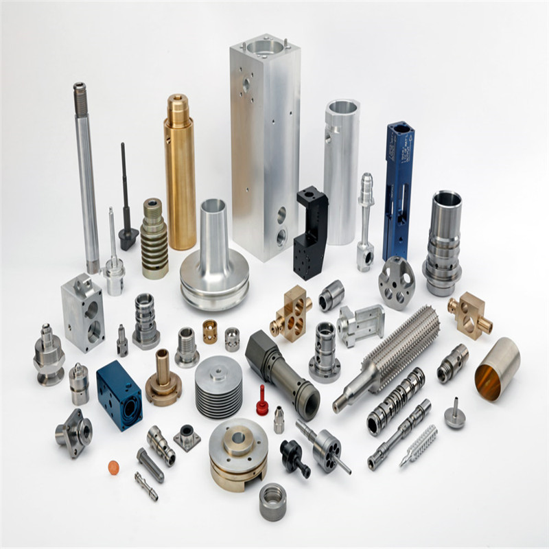
6 mistakes to avoid when designing CNC machinings Parts
1,Avoid Tall, Thin Walls
Wall features on part designs are generally tricky. Cutting tools used in the CNC machines are made of hard, rigid materials such as tungsten carbide and high-speed steel. Nonetheless the tools deflect or bend slightly at machining forces, as does the material they’re cutting. This can result in issues such as an undesirable rippled surface and difficulty meeting part tolerances. The wall also could chip, bend, or break. The taller your wall—our maximum is 2 in. (51mm)—the thicker it may need to be to increase the rigidity of the material. Thin walls of 0.020 in. (0.508mm) or less are subject to breaking during machining and may flex or warp afterwards. Try not to design walls too thick as the cutting tool usually is spinning at 10,000 to 15,000 rpm. A good rule of thumb for walls is a width-to-height ratio of 3:1. Adding some draft to a wall—an angle of 1, 2, or 3 degrees so that it tapers rather than standing vertical—could make machining it easier and leave less leftover material.
2. Avoid Creating Holes That Can't Be Threaded
We can easily add threaded holes to your machined parts. But designing threads so that our quoting software will see them—and so they will get machined into your part—can be challenging. Our quick turn process has a static set of threads available. When our software analyzes your part it looks for a hole diameter that will correspond to one of those threads. If you want a UNC or UNF #5-40 thread, for example, the software looks for a hole with a diameter that’s within the range for that thread. If the diameter isn’t within that range, you won’t be able to assign that thread to your part. This often is when customers call and we when we refer them to our quick-reference Threaded Hole Guidelines page. There you’ll find the types of threads we have available. Click on a particular thread to go to a chart with the range of hole diameters to choose from for that thread. Choosing a diameter that’s 75 percent of the hole drill size—each chart includes that dimension for every thread—will always work. As you’re designing your part, go ahead and use your CAD software’s thread wizard—most customers do. But confirm with our charts that the wizard is outputting a hole diameter that works with our software. Learn more considerations for thread design here.
3. Reconsider Machining Parts That Will Eventually Be Molded
We often see designs for injection-molded parts uploaded to our machining service for prototyping before buying a mold. But each process has different design requirements and the results can differ. A thick machined feature may suffer sink, warp, porosity, or other problems when molded. A well-designed molded part with ribs, pockets, and other features will require prolonged run time to machine. The point here is: part designs are typically optimized for their manufacturing process. Talk to our team first for advice on how to modify your design for a molded part for machining, or simply prototype your parts in their final production process—injection molding. At Protolabs, the initial cost investment for prototype tooling is very low.
4. Avoid Small Pocket Features You May Not Need
Some parts incorporate square corners or small internal corner pockets to reduce overall weight or to accept other pieces of an assembly. Internal, 90-degree corners and small pockets, however, are too small for our larger cutting tools. Creating those means picking away at the corner material with smaller and smaller tools. That could result in using six to eight different cutting tools. All of those tool changes drive up run time— and you guessed it—your project’s cost. To avoid this, first determine how critical the pockets really are. If they are there only to reduce weight, revisit your design to avoid paying to machine material that doesn’t need to be cut. The larger the corner radius you design, the bigger the cutting tool we can use, and the less run time it will take.
5. Avoid Features that Require Unnecessary Machining
One frequent mistake is designing a part with areas that don’t need machine cutting. Such unnecessary machining adds to your part’s run time—run time that’s a key driver of your final production cost. Consider this example, where the design specifies a critical circular geometry needed for the part’s application (see left-side illustration in image at right). It calls for machining the square holes/features in the middle and then cutting away the surrounding material to reveal the finished part. That approach, however, adds significant run time to machine away the remaining material. In a simpler design (see right-side illustration at right), the machine simply cuts the part from the block, eliminating the need for additional, wasteful machining of excess material altogether. The design change in this example cuts machine time nearly in half. Keep your design simple to avoid extra run time, pointless machining—and added cost.
6. Avoid Small or Raised Text
Your components may require a milled part number, descriptions, or a company logo. Or you may think some text just looks really cool on a part. Adding text, though, also adds cost. And the smaller the text, the higher the cost. That’s because the very small endmills that cut the text operate at a relatively slower speed, increasing run time on your part and therefore your final cost. You do have options, however. Cutting larger text goes significantly faster if your part can accommodate it, reducing your cost. And where possible choose recessed rather than raised text, which requires milling away material to create letters or numbers on the part.
- What do we need to pay attention to the plastic mold machining process and machining procedures?
- What kinds of plastic mold materials?
- What is the process of mold manufacturing?
- What should be paid attention to the polishing of injection molds?
- What is easy to ignore when maintaining and overhauling injection molds?
- What are the 6 systems of plastic molds?
- What are the methods of strengthening the surface of injection molds?
- What are the methods of insulation for injection molds?
- How to solve the problem of injection mold release difficulty?
- How can we increase the brightness of ABS injection molded parts?